Precision Z-axis Milling on a RF30 Mill/Drill
By R. G. Sparber
rick.sparber.org
Monday, March 12, 2007
Copyleft protects this document.
Conclusion
It is possible to achieve an accuracy of +/- .000,05" on the Z axis with the procedure presented below. Cuts were mostly done on 6061 aluminum but one was done on CRS with the same result.
This really does sound like an outlandish claim given the typical performance of a RF30 mill/drill. Before you call me a crank, give my procedure a try and see what you get. You probably have all of the instruments at hand.
The Equipment
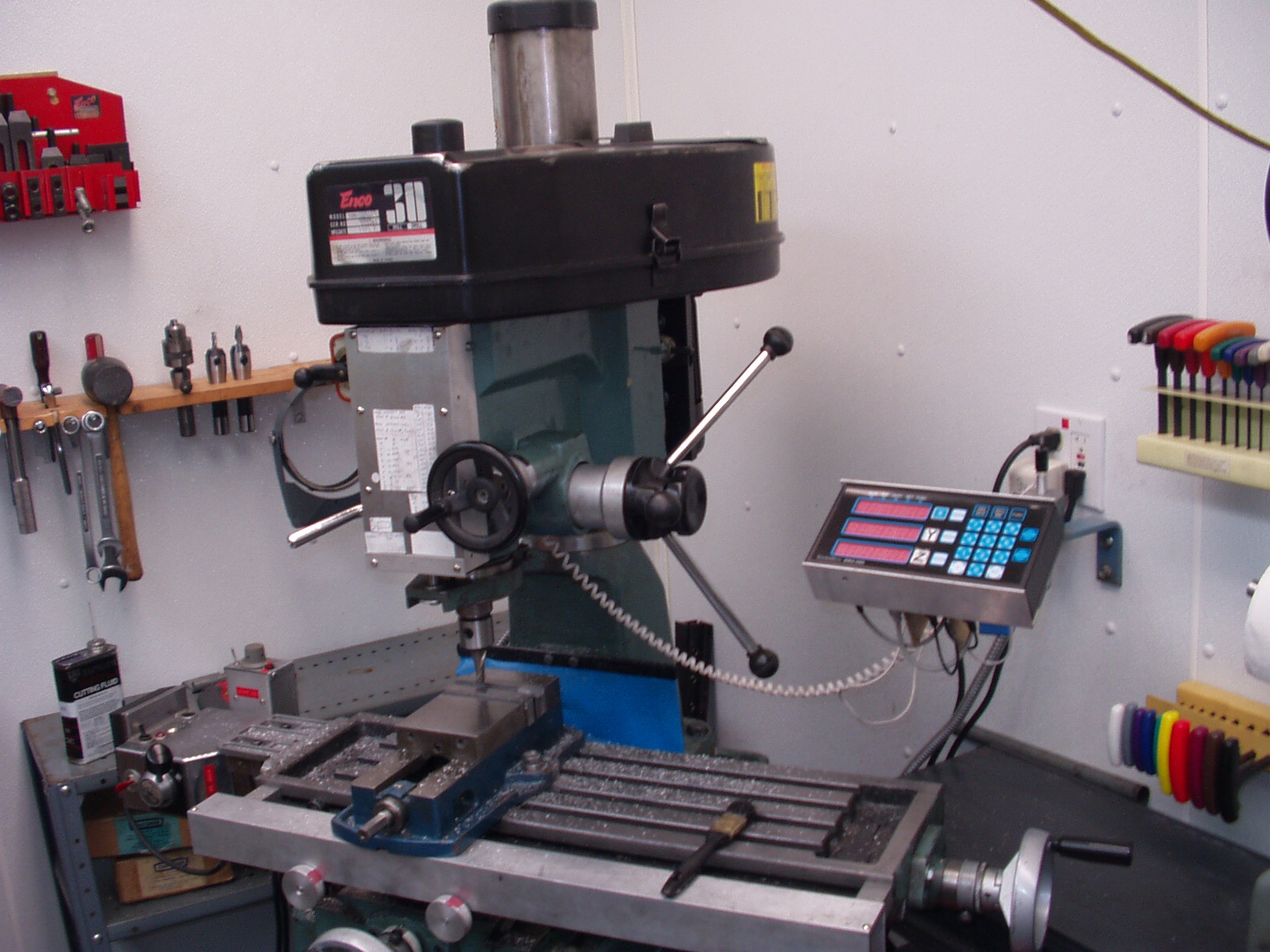
I own an ENCO RF30 mill/drill that is outfitted with a Shumatech Digital Read Out (DRO). The mill/drill is lightweight compared to a Bridgeport so it is reasonable to assume that its accuracy will be "poor", what ever that means. The DRO is potentially as accurate as the Chinese scales that feed it. These scales have an advertised accuracy of +/- .001" with the ability to display either 0 or 5 in the forth digit to the right. I use the DRO to get within .01" of my target value on the Z-axis and then employ the procedure presented below. The DRO is still used but not in the conventional manor. If you do not own a DRO, then a plunger Dial Test Indicator (DTI) will work fine.
Needed Instruments
There is a commonly accepted truth when it comes to accuracy. You can measure with better accuracy than you can cut.
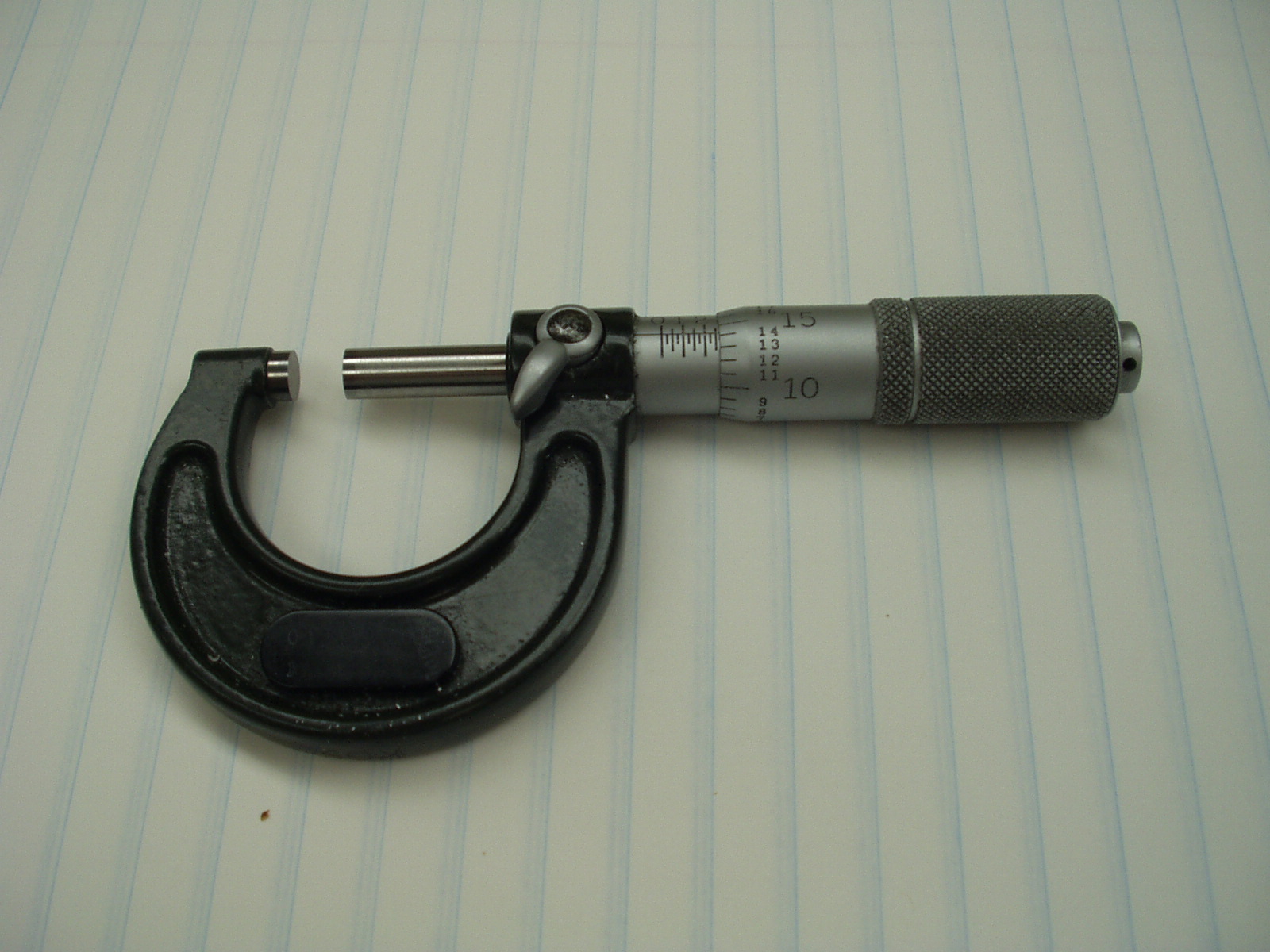
My primary instrument for measurement is a no name 0 to 1" mic that reads out to the nearest .0001". It takes a bit of practice to get repeatable results since it is easy to over tighten the barrel of the mic and read a smaller number than actually exists. As far as my little hobby shop is concerned, this mic is my ultimate standard. Since I can't read closer than to the nearest .0001", it is impossible for me to machine better than this value even if my mill/drill was perfect.
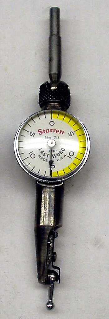
An essential part of the procedure is to know when you touch down on a surface. For this I use a recently reconditioned finger DTI from Starrett®. You will also need a solid means of clamping the DTI to the spindle.
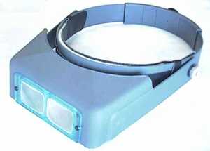 The DTI is only as accurate as your ability to see it, so I use an Optovisor® while I set the needle over the zero mark. The DTI's needle is the same width as the tick marks on the dial face. With the help of the Optovisor, I can move the needle until it seems to vanish into the tick mark. It does take a lot of patience and steady hands to attain this alignment but the resulting accuracy is amazingly good.
The final instrument is a standard parallel with a small modification. I took a 1/2" tall parallel from my low cost set from ENCO and added a cylinder bolted through one of the holes.
The cylinder has a shoulder turned on it so there is a snug fit into the hole of the parallel. The bolt is fed through the parallel and into a tapped hole in the cylinder. This cylinder extends below the bottom of the parallel by about .020".
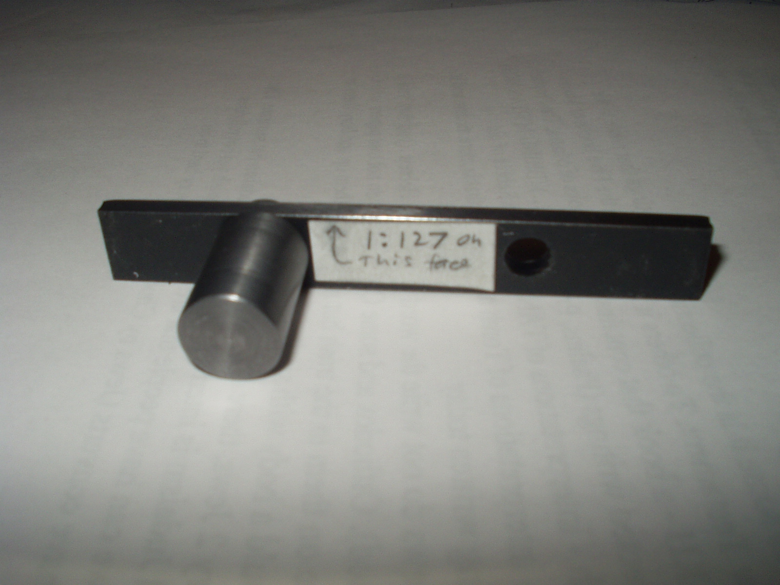
The goal is to make a sine bar with a slope of around 1:100. Mine came out 1:127, which is just fine. The error was due to the fact that the hole is not centered but I assumed it was. The critical bit is that the top surface of the parallel be perfectly flat and that the slope be accurately known. The best way to measure the slope is to measure the height at each end and divide by the length of the parallel.
The "Trick"
There is a standard trick when using a lathe for gaining high precision using the compound. 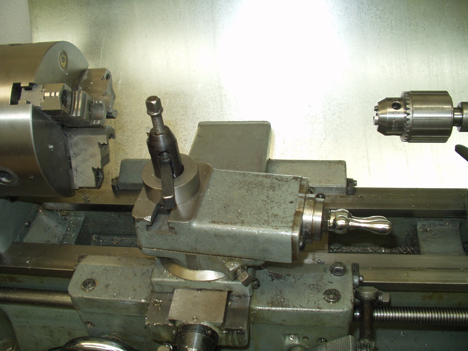 You simply set the compound so the feed is almost parallel to the ways. A large feed-in on the compound results in a small feed into the work. I'm sure this trick is as old as the compound.
Well, it turns out we can do a similar trick on the mill. Remember that sine block? Say it has a slope of 1:100. Then for every .010" we move along its base, we move .010"/100 = .0001" vertically. A decent plunger DTI or DRO can give you an accurate .010" motion so we are half way there. The other piece of the puzzle requires us to reliably contact this sine bar. That is where the finger DTI and Optovisor come in.
Put it all Together
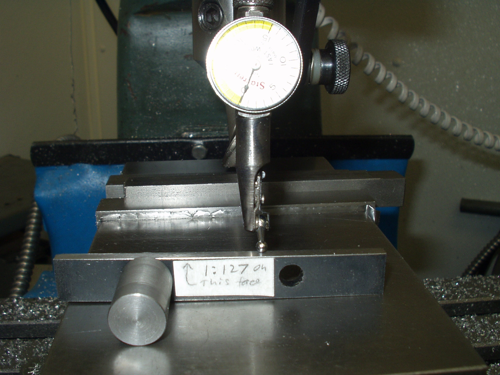
Say I want to move the cutter down by .0050". The quill will be locked from the previous cut. I first clamp the DTI to the spindle. The dial face is turned so that a rotation of 2 tick marks brings us to zero. This minimizes the force on the DTI support so minimizes its deflection. Then the DTI is carefully moved down until it almost touches my sine bar. The sine bar can be slid over the top of the movable jaw of the mill vise until the DTI reads zero. Be careful not to let the bottom end of the sine bar fall off of the jaw. Alternately, you can move the X-axis feed to zero the DTI. Note that the DTI is positioned for direct viewing. Any parallax would greatly increase error. We now have contact on the sine bar. Next I move the table to the left a distance of (.0050") x (127) = .635". Since I have a DRO, this is a simple matter. If I were using a plunger DTI, it would take a little set up time but is not hard to do. You may be able to just use the calibrated dials if you know them to be accurate. Note that an error of +/- .002" on the X-axis will cause an error of +/- (.002"/127) = .000,002" on the Z-axis. In other words, other errors will completely obscure small errors in positioning the X-axis.
There is now a gap between the finger of the DTI and the top of the sine bar.
Now comes the part that will make or break your accuracy plus will try your patience. Unlock the quill and carefully feed down until the DTI again reads zero. As you again lock the quill, the DTI will probably move. Note the shift and try to anticipate the shift. With practice you will be able to tighten the lock and watch the needle swing into perfect alignment with the zero tick mark. Sometimes it takes me ten tries to get it right but the reward is at hand. I now have the spindle .0050" lower. At least in the learning phase, you may wish to just get the DTI close and then move the table until it reads exactly zero. Read the X-axis movement and calculate the expected down feed. For example, if I ended up with a table movement of .654", then the expected down feed is .660"/127 = .0052".
Error Sources
There are two categories of error associated with the mill/drill - static and dynamic.
Static error comes from an imperfect vise, poor technique in placing the block to be machined down on its parallels, and how close to parallel the spindle is to the Z-axis. Some of these topics are addressed in other article on my web site.
Dynamic errors are much harder to see. Even before the cutter hits metal, motor and belt vibration cause the mill's head to bounce up and down. I have spent a lot of time looking at Z-axis cutting so know it bounces up and down. In the near future I will start to look at side to side bounce and how it effects X and Y cutting.
When I started this part of the journey, I was running the same V belts that came with the machine over 15 years ago. Talking with friends with far more experience than me, I was guided to buy link belts.
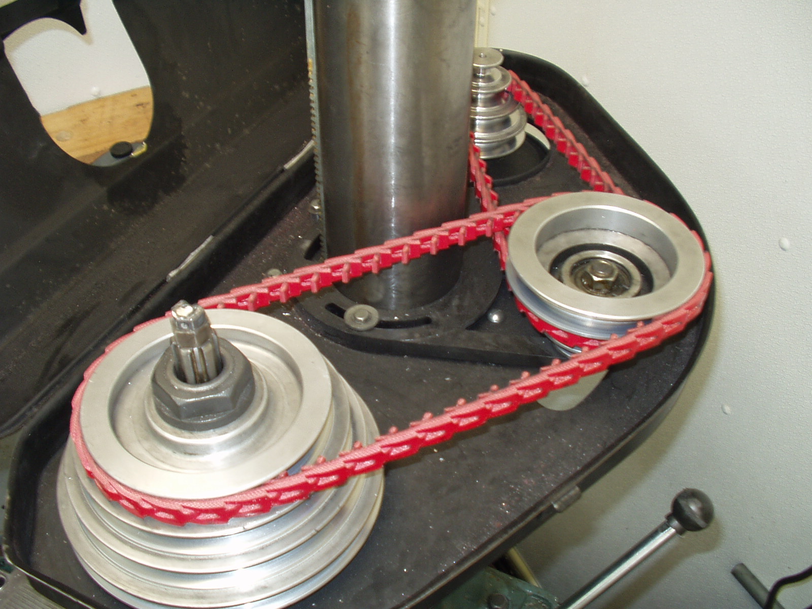
They greatly reduced the vibration and seem to improve the finish.
An easy way to see the effects of head vibration on Z-axis accuracy is to touch the cutter gently down on the surface of a test block that has been machined flat. Set zero and raise the cutter. Then move the cutter off of the block, feed in .005" and cut the surface. Stop the cutter and again gently feed down to the surface. When I do this, I see about .002" of travel. This says that the head is bouncing up and down .002" during cutting sort of like a sewing machine needle. If you are trying to hit .01", this is no big deal. In my quest for the best accuracy, this error source has got to go.
Another dynamic error source is contamination. As you cut, you are generating flecks of metal. They go everywhere. When the block being machined is removed from the vise, there is a tendency for these flecks to settle on the top of the parallels and on the fixed jaw of the vise. These flecks may only be .001" thick but that is a bolder when you are chasing tenths.
My claim is that I can cut the thickness of a block to a given accuracy at a given point. This does not mean that the plane defined by the bottom of the block is parallel to the plane defined by the top of the block. My procedure actively works to cut the thickness at the given point. Your ability to cut parallel surfaces comes into play for the rest of it. Factors such as vise ways parallel to the XY plane, spindle parallel to the Z plane, a true vise, clean surfaces, true parallels, and proper bedding of the block contribute to your overall success in this matter.
Error Source Remedies
We know that vibration causes head bounce, which causes the cutter to go deeper than indicated by your down feed indicator. I can't tell you exactly how much vibration exists but am reasonably sure that given two consecutive cuts of the same depth, cutter RPM, and feed rate, the vibration will be almost identical. As you will see in the procedure, it is possible to reduce the vibration error to a point where other factors dominate.
One problem I had when trying to feed in .0001" was the gunge in my down feed mechanism. The congealed grease from 15 years of use had gotten sticky. It was a simple task to disassemble, clean, and re-grease.
When you are trying to chase these tiny numbers, it does not take much to really mess you up. After you made a light cut, there will be lots of tiny flecks of metal on the mill and possibly on your hands. If one of these flecks gets under the block or between the block and your mic, you can get a substantial error. The solution to this problem is to become a fanatic about cleanliness. Now don't laugh, but I keep a roll of toilet paper and a spray bottle of WD40 next to my mill. Every time I remove the block from my vise, I spray down all surfaces with WD40 and wipe down with clean TP. Use a clean face of TP on each wipe of the vise or you will re-contaminate surfaces. Use the same procedure on your mic anvils. Lastly, be mindful of metal particles on your hands. I do not like to wash my hands in WD40 but do try to wipe them clean with just TP. If they are really coated with metal particles, I use waterless hand cleaner. This stuff works well but does not know the difference between unwanted grease and normal hand oils. After I use waterless hand cleaner, I wash my hands in soap and water and apply hand cream. I have it on good authority that "Complex 15®" works best. I expect to buy some in the near future. Trying to work with cracked and bleeding hands is no fun and is avoidable.
The Procedure
Not included here is the fact that all surfaces must be kept absolutely clean.
Block preparations
Finish cut
End of procedure.
Final Thoughts
I invite people to try this procedure and let me know what they learn.
I would like to thank Brian Lamb for his guidance on this adventure. He keeps me honest and on my toes. I would also like to thank Lawrence Gill for his sage advice on skin care. I have been to many dermatologists and none were as helpful. My days of cracked and bleeding hands due to the ravages of degreaser are over.
Enjoy,
Rick Sparber
Rgsparber@AOL.com