Drawbar with Integrated Spindle Lock
By R.G. Sparber
November 21, 2006
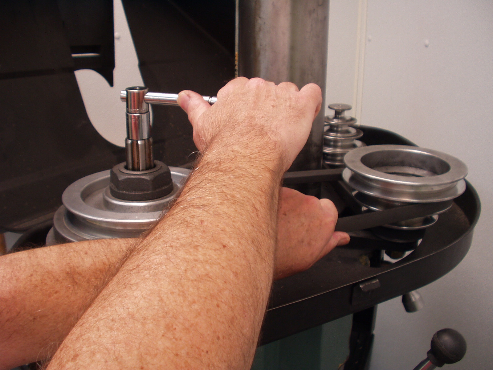
My RF-30 mill/drill has no spindle lock. To tighten the drawbar I must hang onto the drive belt with one hand while turning a wrench with the other. It is an awkward maneuver and if the belt is on a small diameter step of the pulley, the spindle tends to slip. See Picture 1.
Picture 1
Over the years many solutions to this problem have been offered and deferred. I was holding out for a really simple solution. One day, that solution popped into my head – a double nut drawbar. The top nut is fixed to the drawbar and the nut below it is threaded on the drawbar. I build it and excitedly tried it out. Unfortunately, it did not work. Oh well, time to put it aside and let it "cook" a bit more. Sure enough, the next morning a modification came to me in a flash. This time it worked. I’m glad I did not give up after the initial failure. The design change was small but critical.
Consider the operation of a standard drawbar. You tighten the nut on top. It is firmly connected to the drawbar shaft so the drawbar turns. At the bottom of the shaft is a threaded section that engages the collet with its internal threads. As you turn the nut, the collet is pulled up into the spindle. Before it gets tight, the bottom of the nut starts to press and turn against the top of the spindle. This causes the spindle to turn. Only by stopping the spindle rotation can you successfully resist this torque and tighten the drawbar.
So we need the drawbar nut to turn and push down but not rotate the spindle. The trick is to add a non-rotating washer between the bottom of the drawbar nut and the top of the spindle. See Figure 1. The nut has both a rotational force and a downward force. The non-rotating washer counters the rotational force while the downward force is transmitted through the fixed washer to the top of the spindle.
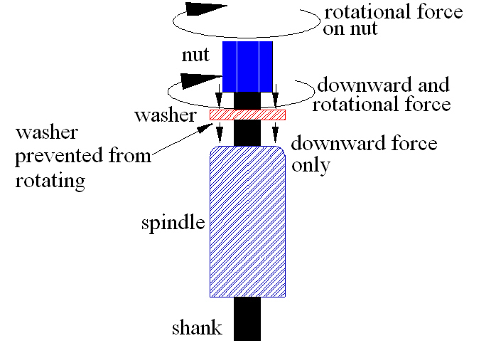 Figure 1
One way to prevent the washer from rotating is to cut flats on the outside like a nut and then put a wrench on it. I call this part a Washer/nUT or WUT (pronounced… "whut"). As the nut is turned, it pushes down and tries to turn the WUT. But the WUT is prevented from turning by a wrench that holds it steady. The downward force of the nut is transmitted through the WUT and onto the top surface of the spindle. The upward force of the collet being pulled into the spindle counters this downward force.
Figure 2 shows the plans for the drawbar that fits my mill/drill. I own a socket and T handle for the old drawbar nut so used those dimensions for the new drawbar nut to avoid buying new tools. A flange was added to the bottom of this nut to prevent the socket from sliding down too far. Below this nut is my WUT. I chose its dimensions so a closed end wrench could easily slide past the nut. It is also the same size as my hold down nuts so I don’t need to buy yet another wrench. The drawbar nut is either pinned or plug welded to the draw bar. The WUT is a sliding fit. Your drawbar may differ. Make the new drawbar ½" longer than the old one to allow for the WUT. Verify the thread pitch and diameter of your bar before you start construction.
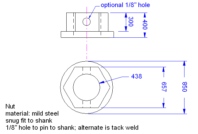
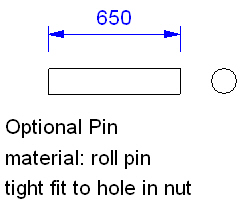
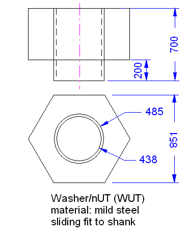
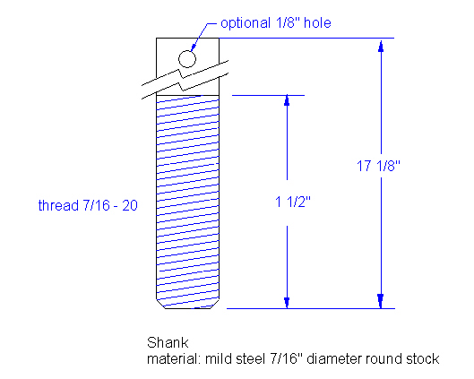
Figure 2
The nut and WUT were first turned on the lathe to the correct diameter. I then moved to my mill/drill and cut the flats using a spin collet. The threads on the drawbar were single point turned on my lathe and a die was applied to clean up the threads. The first thread was filed such that only full width threads exist. Take care that the bottom of the nut and the top and bottom of the WUT are square on the drawbar rod. If these mating surfaces are not square, the rod will bend during tightening. If you wish, the drawbar nut and WUT can be made by drilling out standard nuts. A washer between them will provide the flange.
Picture 2 shows the new drawbar with its WUT next to my original drawbar. Notice that the new drawbar is longer to compensate for the thickness of the WUT.
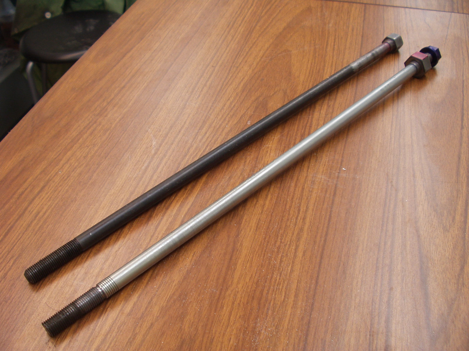
Picture 2
Picture 3 shows the new drawbar installed in my mill. Color on the nut and WUT has been added for clarity.
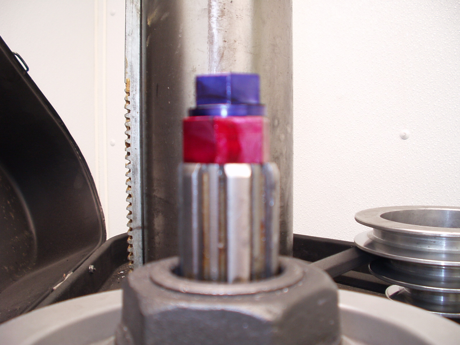
Picture 3
In picture 4 you can see my closed end wrench and T nut handle with socket ready to tighten the drawbar. I center the crossbar of the T handle to act as a flywheel as I spin the drawbar into the collet.
Picture 4.
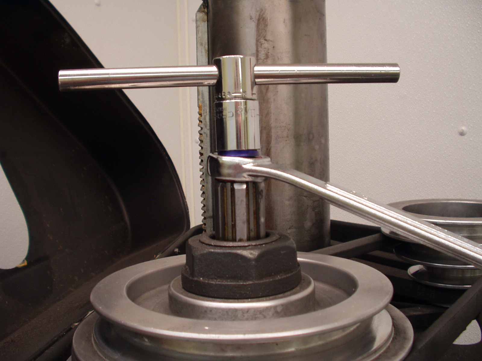
Picture 5 shows the drawbar being tightened. Plenty of leverage and no grabbing of the drive belt.
Picture 5.
When done, simply remove the tools, close the belt cover and start making chips.
Rick Sparber