Single Iteration Mill Vise Alignment Procedure
By R.G. Sparber (rgsparber@AOL.com)
Math independently solved by Phil Burman (
phillip.burman@lyse.net), Martin Connelly (martin.connelly@siemens.com), and Steve Koerner (sjkoerner@gmail.com)
Background
Aligning a vise on a mill can be frustrating and time consuming. Many solutions have been employed over the years that speed up the process. One common solution is to machine a bar that is a snug fit in the T slot and attach the bar to the vise’s base. Assuming the T slot sides are true and smooth, aligning the vise simply requires dropping the vise with attached bar into the T slot.
A variation of this idea is to clamp a plate into the vise’s jaws with pins pointing downward which engage the T slot. This approach has the advantage of being removable when not in use or when you want to set the vise at other than parallel to the X-axis. I have tried this latter approach and found it accurate to within 2 thou on my Enco RF 30. I am unwilling to give up that many thou of accuracy. I believe that this 2 thou error comes from the rough sides of my mill’s T slots.
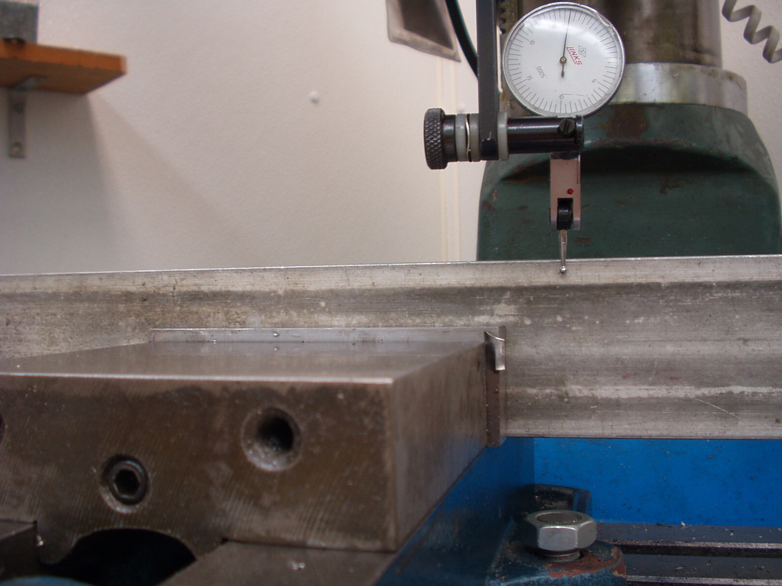 A different set of approaches involves replacing one of the holddown bolts with a pivot pin. We can then place a perfectly square block of metal in the vise such that the reference face intersects the pivot point. Note that the Dial Test Indicator’s (DTI’s) finger is positioned directly above the center of the pivot pin. The DTI is zeroed. Call this point Touch Down point Right (TDR).
 The mill table is then moved such that the DTI is on the other end of the bar. The farther apart the two readings, the better the accuracy (recall that the bar is perfectly square). Call this Touch Down point Left (TDL). The vise is then rotated until the DTI again reads zero.
This procedure is very quick and simple. Too bad it has a problem: where to get the perfect alignment bar? Any error in the bar directly translates into error at the vise jaws. The simple fact is that if you want to set the vise jaws true, you must indicate the vise jaws directly.
A Slightly Different Approach
The problem with directly indicating the vise jaws while using a pivot pin is that the TDR and TDL points move in an arc around the pivot point. So if you set zero at TDR and then move to TDL, the error measured is not the amount to move TDL. It was true with the perfect alignment bar but not now. However, through the magic of trigonometry, there is a small equation that will permit us to indicate directly on the vise jaws and use the pivot point.
 First, let us define two constants that describe your vise. The distance from the center of the pivot pin to the TDR point along the X-axis is R. The fixed jaw width is W. On my 4" Enco vise, R = 0.7", and W = 4".
These numbers can go into any of the equations developed by Phil, Martin, or Steve. I will present Martin’s equation, which is accurate enough for the range of values you can read on a DTI. We will return to these equations after discussing the pivot pin and T nut shim.
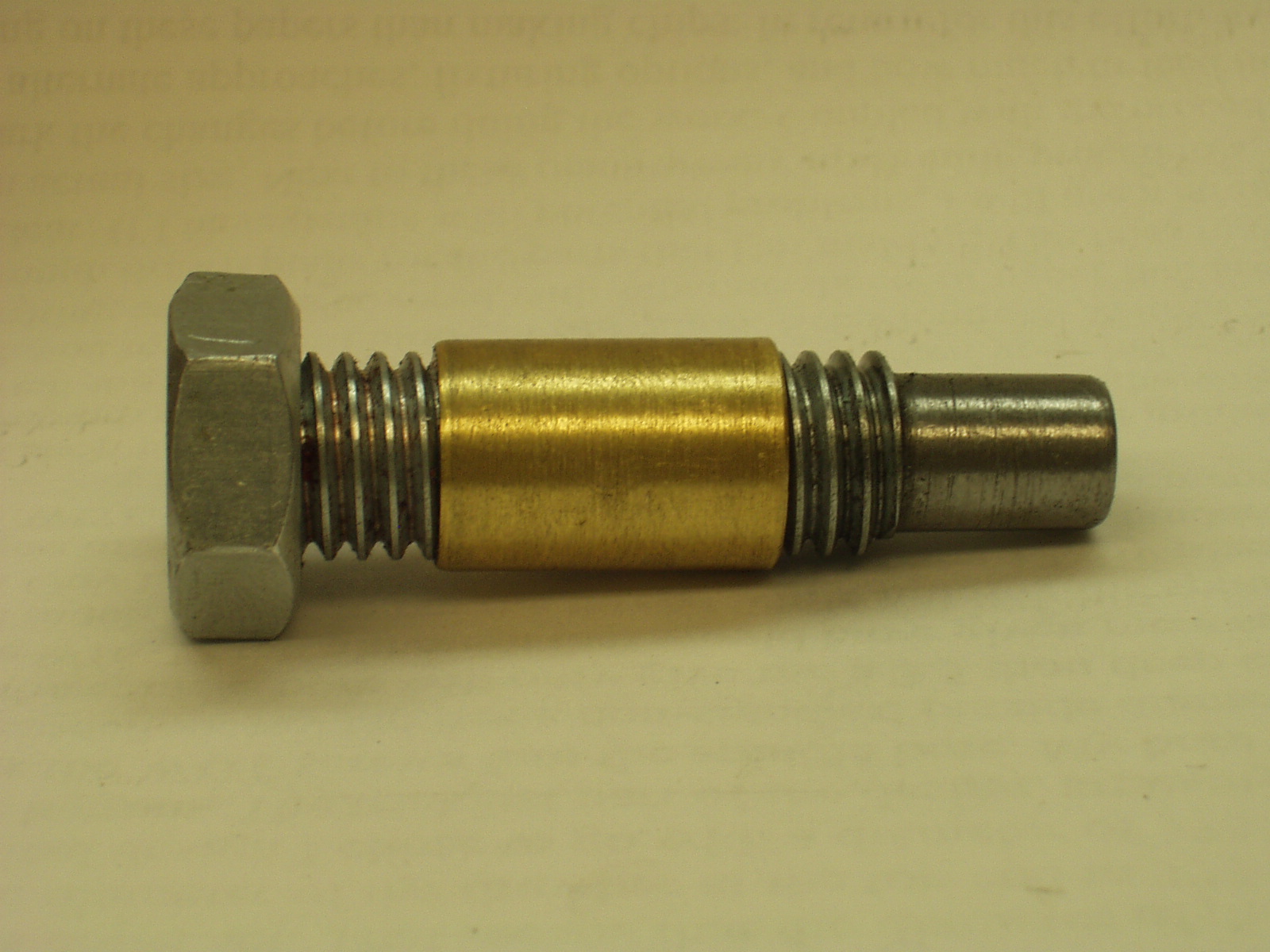 Alignment accuracy depends on having the vise pivot about a fixed point. This is accomplished by making a pivot pin. The body of the pin is made from threaded rod that matches your T nut. The bottom of the body is turned so it passes through the bottom of the T nut. The bottom end of the body is cut square so when the pivot pin is tightened down, it sits vertically and also locks the T nut in place.. In the center of the body is a brass bushing. I turned some brass rod to the ID of the vise hole. The inside of the brass rod is drilled and tapped to fit the body. Clean all surfaces and Loctite in place. The top of the pivot pin has a nut Loctited in place. In this way you cannot over tighten the nut. The nut will turn before you destroy the T slot.
 When it is time to align the vise, remove the right bolt and insert the pivot pin. Note that the nut does not touch the top face of the vise ear. We want to pivot the vise, not clamp it down yet. If you find any play in the pivot pin, simply press your thumb on the front face of the vise ear when you set TDR and read TDL.
During the following procedure you will read a DTI value at the TDL point. This value is fed into the equation resulting in the new DTI value. For example, say at TDL you read –5.0 thou. Call this number "m". You feed "m" into the equation and the result is +0.9 thou. The vise is then rotated until the DTI reads +0.9 thou at TDL. The vise jaw is then parallel to the mill’s X-axis.
The equation:
n = (-R/W) * (m)
where R and W are defined in the above figure
m is the value read on the DTI at Touch Down point Left (TDL) after the DTI is zeroed at Touch Down point Right (TDR)
n is the value you must read on the DTI while it is at TDL after the vise is rotated
For example, on my vise if I read -5 thou at TDL, then I must rotate the vise until the DTI (-0.7/4) * (-5 thou) = +0.9 thou.
I suggest you make a table showing the measured DTI value at TDL ("m") and the DTI value after the vise is rotated ("n"). Here is my table:
|
m, thou |
n, thou |
|
0 |
0.0 |
|
-0.5 |
0.1 |
|
-1 |
0.2 |
|
-1.5 |
0.3 |
|
-2 |
0.4 |
|
-2.5 |
0.4 |
|
-3 |
0.5 |
|
-3.5 |
0.6 |
|
-4 |
0.7 |
|
-4.5 |
0.8 |
|
-5 |
0.9 |
|
-5.5 |
1.0 |
|
-6 |
1.1 |
|
-6.5 |
1.1 |
|
-7 |
1.2 |
I copied this table onto a blank address label and then stuck the label onto a piece of flexible magnet. I get these magnets in the junk mail about once a month. Then I trimmed around the label to make a small reminder note. The note sticks on the head of my mill along with other reminder notes.
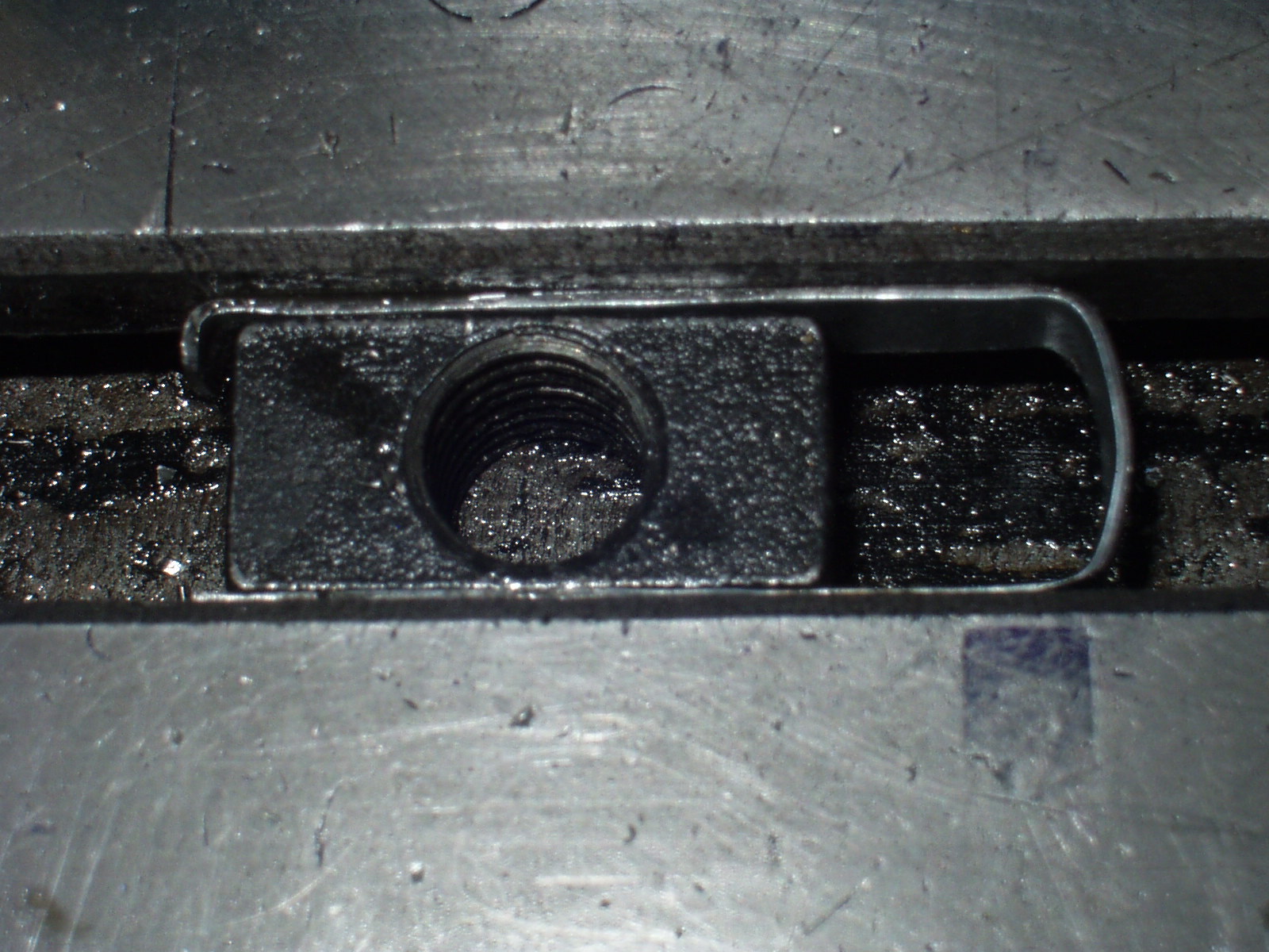 There is one more part worth mentioning. In order to permit a full range of motion for the vise, it is good to center the pivot point in the T slot. I did this by making a U shaped spacer that wraps around the T nut. The spacer slightly wraps around the left end of the T nut. In this way it is easy to pull on the loop on the right side and pull the nut from under the vise ear.
DTI Accuracy Warning
A word of warning about using a finger type DTI. Maximum accuracy is when the force on the finger is perpendicular to the finger. The larger the dial reading, the further from perpendicular you become. If the reading is inaccurate at TDL, the correction will also be off. I suggest you keep your alignment readings below 7 thou.
Alignment Procedure
remove the right hold down bolt and replace it with the pivot pin; snug down; loosen the left hold down bolt
roughly align vise by eye
set the DTI to zero at TDR
If the rough alignment is not good enough, you will run out of travel on the DTI before you reach TDL. If it looks bad,
- Move the DTI to the left a distance R as defined in the figure. This makes the equation n = -m. So read the DTI value and rotate the vise until the DTI reads the negative of this value.
- return to TDR and reset the DTI to zero
- move the DTI to TDL and read the dial
- refer to your table for the final value
- rotate vise till DTI reads this value
- tighten the left bolt
- replace the pivot point with the right bolt and tighten
The first time you use this procedure be sure to check the fixed jaw after you tighten the hold down bolts. If you find that the vise has shifted, understand that some of the downward force of the bolts is being diverted to lateral force. A bent washer may be the problem. Another possible error source is if the tops of the vise ears are not parallel to the table face. If these look fine, remove the vise and verify that the bottom of the vise and the table clean.
Additional Accuracy
If your DTI has major tick marks at each thou, it may be hard to see a tenth. One way to improve your accuracy is to put a bar in the vise that is longer than the vise jaws. You can then indicate the jaw at TDL and then move to the end of the bar with your DTI. Scale the change in DTI value after vise rotation for the longer arm. For example, say you read –5 thou at TDL and the equation tells you to move to +0.9 thou. This is a change of +5.9 thou. If the end of the bar is twice as far from the pivot pin as TDL, then you can go to the end of the bar and move 2 x 5.9 = +11.8 thou. It is easier to see a change of 11.8 than a change of 5.9.
Acknowledgements
The equation used in this article is simple. This simplicity did not come easy to me. My attempts at solving the math generated many pages of equations but no usable results. My hat off to Phil, Martin, and Steve for not just solving the problem but also driving it down to this elegantly simple form.
Questions and comments are always welcome.
Enjoy!
R. G. Sparber
Rgsparber@AOL.com
October 27, 2006