Why is one Parallel always Loose?
By R.G. Sparber
January 16, 2007
Copy left protects this article.
You know for a fact that the block is square and dead flat. Yet when you put it into your mill vise on top of two parallels, one parallel is always loose. Doesn't seem fair! The explanation can be found in geometry. It all boils down to points and lines.
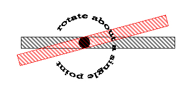 First consider a single point and a line extending out from it. This is a "one-dimensional" world. I constrain the line to pass through the point. The line is free to rotate about this point. Not terribly interesting to be sure. Next consider constraining the line to pass through two points.
 The line is now unable to rotate. We can put the two points anywhere along the line and not change its position. OK, still not terribly interesting. But what if we add a third point.
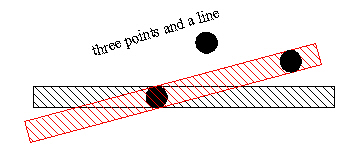 The line is held in place with the first two points. The only way that the third point can be on the line is if it perfectly lands on the line. If you try to define a straight line with three arbitrary points, you may have a problem. We call this problem an "over constrained system". Geometry wins out - the line will be defined by two of the points and the third point will not fit. In the real world we do have examples of over constrained systems. In these cases the "straight" line bends or the third point is forced into position. Often this is seen as a binding up of the mechanism.
For a one-dimensional line, it takes two and only two points to define it.
We can have a similar situation with two-dimensional lines. While two points are necessary and sufficient in a one-dimensional world, three points define a two dimensional line. Consider a line that forms a right angle.
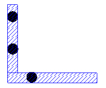 If we only look at the vertical portion of the line, the two points constrain motion to up and down. When we consider the horizontal portion and the third point, the line is fully constrained. It cannot move up and down or sideways.
For a two-dimensional line, it takes three and only three points to define it.
It turns out that three points also defines a plane. If you take a block and place it on three points, it will sit there nice and solid. 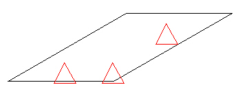 Adding a forth point and the block may rock back and forth. That rocking is an indication of an over-constrained system. In one position three out of the four points are supporting the block. In the other position, the one that did not touch the first time replaces one of the original three points.
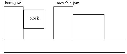 Consider a block that is squarely pushed up against the face of the fixed jaw of your mill vise. In fact the block is more than likely contacting at only three points. Other points may be a microscopic distance away but they most likely do not touch. Adding a piece of paper between fixed jaw and block acts as a filler material and greatly increase the contact surface. You will note a proportional increase in gripping strength.
When you close the vise, the movable jaw is able to pivot slightly in order to try and contact the block. If the block is too far from square, it may not be possible for the movable jaw to fully make contact. If you have this condition, be aware that the block is not secure and can fly out of the vise during machining.
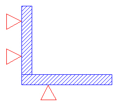
We are now ready to consider the case of having one versus two parallels to support the block. This can be explained in two dimensions as shown here. The two triangles on the far left represent contact points between fixed jaw and block. These contact points set the vertical segment of the line. Our single parallel represented here by the bottom triangle sets the horizontal segment. Our two dimensional block is supported by three points so will be solid. This is not an over constrained system.
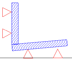
In order to illustrate the effect of a second parallel, I have exaggerated the defect in our two dimensional block. Our first parallel happens to contacts the block but the second parallel does not. With the vise open, we can push down on the block and contact both parallels at the same time. The block can more than likely be made to rock back and forth between contacting the fixed jaw and contacting the two parallels. No amount of tapping with a mallet is going to give you full contact on both the fixed jaw and both parallels with the vise closed unless you manage to beat the block into submission. Not a pretty sight.
If you now think in three dimensions, the block will contact the fixed jaw at three points while it contacts the parallel at two points. These five points completely define the location of the block. If any other points contact the block, they must fall exactly on the X, Y, and/or Z planes defined by our five points.
So the next time you find that one parallel is snug and the other is loose, don't think it is anything you are doing wrong. It is simply your over-constrained system getting even with you.
I welcome comments on this article. All of us are smarter than any one of us.
Enjoy,
Rick Sparber
Rgsparber@AOL.com