
Error Chasing on a RF30 equipped with a Shumatech DRO
Or, Trying to make a silk purse from a sow's ear
By R. G. Sparber
Rick.sparber.org
Friday, March 02, 2007
Copyleft protects this document.
Note: This article contains preliminary data that may later turn out to be
bogus. I wanted to get something out to the community quickly just in case my long-term study supports these early findings.
Conclusion
I'm sure you do not want to read all the way to the bottom before figuring out if there is anything of value in my ramblings. So, without delay, here are my
preliminary findings.I made 5 consecutive cuts in a block of aluminum using the procedure described within these pages. On each cut I first used my mic to measure the block's thickness. Then I set the cutter depth and made one pass through the metal. A second reading of thickness was made with the mic at the same point on the block. The change in mic readings was then compared to the set value. In an attempt to be at least a little scientific, I did not calculate the amount I lowered the cutter until after reading the mic. It is just too easy for me to unknowingly change the force on a mic a tiny amount if I am close to a desired value. I estimate that my procedure has an uncertainty of +/-.0002".
|
Pass |
Set depth of cut |
Measured cut |
Error |
|
1 |
.0021" |
.0021" |
0 |
|
2 |
.0025" |
.0025" |
0 |
|
3 |
.0031" |
.0031" |
0 |
|
4 |
.0033" |
.0031" |
.0002" |
|
5 |
.0030" |
.0029" |
.0001" |
I am certainly skeptical of these results. They look too good to be true. One of my motivations for publishing this early data is to see if others can reproduce it.
The Equipment
I own an ENCO RF30 mill/drill that is outfitted with a Shumatech Digital Read Out (DRO). The mill/drill is very light weight compared to a Bridgeport so it is reasonable to assume that its accuracy will be "poor", what ever that means. The DRO is potentially as accurate as the Chinese scales that feed it. These scales have an advertised accuracy of +/-.001" with the ability to display either 0 or 5 in the forth digit to the right.
It could be argued by those with commercial equipment that my set up is a "sow's ear". This inspires me to see just how accurately I can cut a block of metal and maybe get a "silk purse" out of it.
There is a commonly accepted truth when it comes to accuracy. You can measure with better accuracy than you can cut.
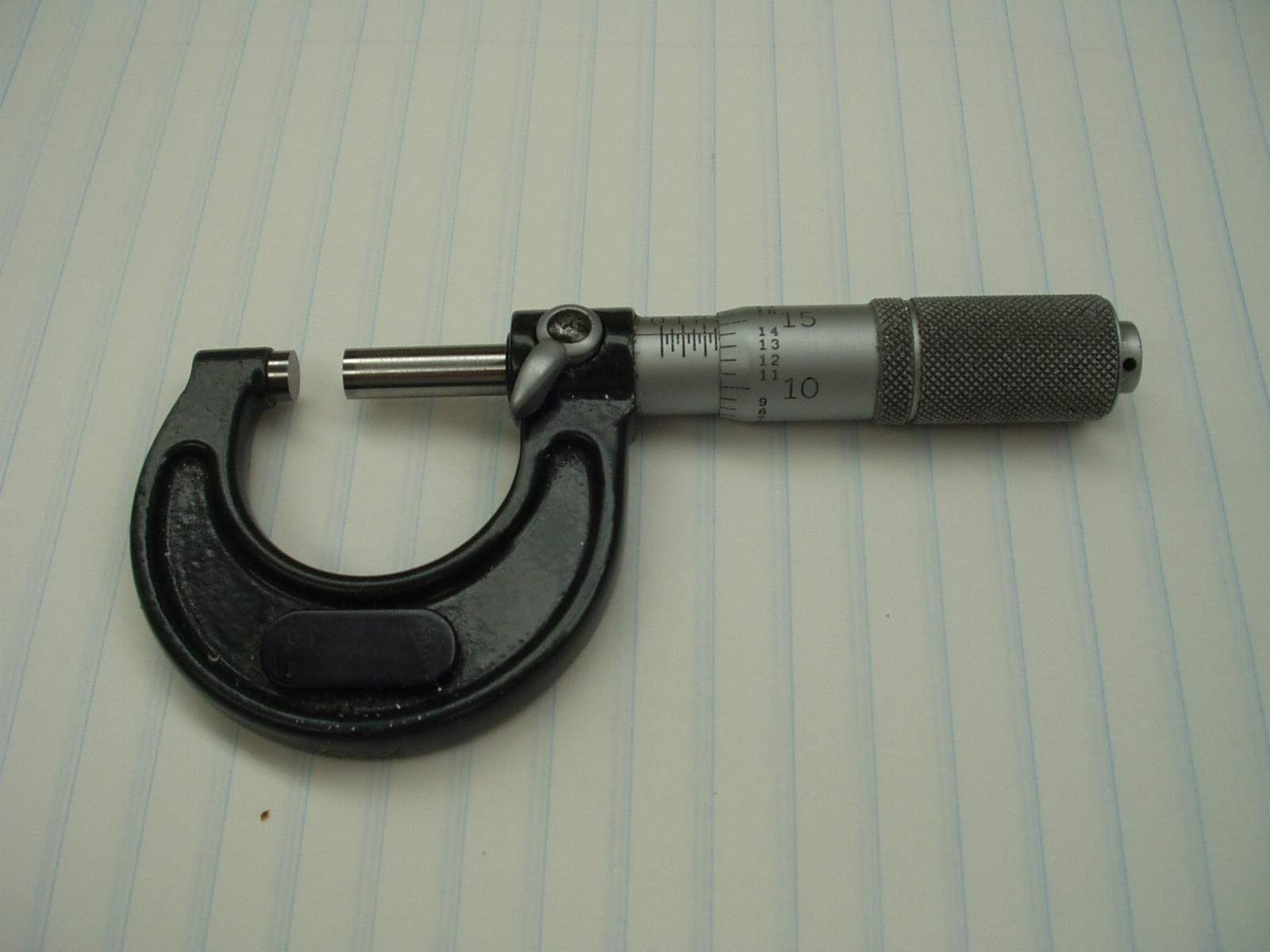
My primary instrument for measurement is a no name 0 to 1" mic that reads out to the nearest .0001". It takes a bit of practice to get repeatable results since it is easy to over tighten the barrel of the mic and read a smaller number than actually exists. As far as my little hobby shop is concerned, this mic is my ultimate standard. Since I can't read closer than to the nearest .0001", it is impossible for me to machine better than this value even if my mill/drill was perfect. As you will see, trying to cut to within +/- .0002" is something of a minor miracle and I'm not yet convinced it is possible.
Error Sources
At first glance, it appears that my DRO has no error because it is all digital. All error comes from the scales. This turns out to be false. The DRO does have two error sources.
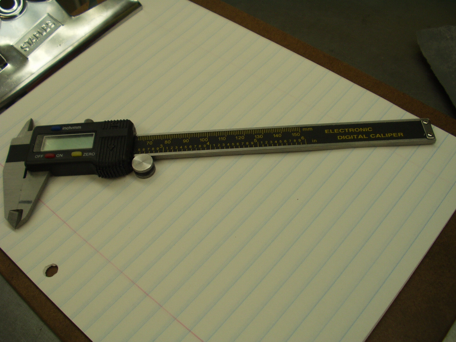
The first error source is a trade off between display flicker and uncertainty. If you look at the numbers coming directly from the scales, you will see that they jump around constantly in the least significant digit. You never see this digit on a typical digital caliper that reads to the nearest .0005". If you try to read much closer than .0005", the jitter of these numbers will drive you crazy. The solution is to add a software-based filter inside the DRO. This filter outputs the same number as long as the numbers coming in from the scale are within +/- of a programmable value called the threshold. Without this filter the displayed numbers would flicker making any meaningful reading impossible. In essence, the filter gives you a solid reading in exchange for an uncertainty. For example, I have my threshold set to 9, which translates into an uncertainty of +/- .00044". In exchange for this uncertainty, the display is steady. I accept this trade-off but it does not make me happy. You will see later that I found a way around this limitation.
The second error source took a bit of head scratching. As I move one of my scales in increments of .0001", I can see the DRO's display jump from .0000" to .0005" and then to .001". To my surprise, it stays at .0000" until I have gone .0005". Then the display jumps to .0005". It stays at .0005" until I reach .001" at which point the display jumps to .001". In other words, the software is rounding down. This introduces an average error of .00025". In my quest to make that "silk purse", this error has got to go. As you will see, it can be removed.
Before I get attacked at this point, let me talk about accuracy, precision, and short-term accuracy. The scale manufacturers commonly say that their scales are accurate to +/- .001" but readable to +/- .0005". They are giving us more precision than accuracy. By using a known reference, like my mic, it is possible to take advantage of the precision. I own a set of ground 1-2-3 blocks. The 1" dimension mics out at 1.0000". When I measure it with my digital caliper, it usually reads between .9995" and 1.0000". I get the same variation using my DRO when I use a Dial Test Indicator (DTI) as the edge finder. So I must have gotten lucky and my digital scales are well within their advertised accuracy. For those times when absolute accuracy is important, I use these 1-2-3 blocks to test my DRO's accuracy.
The remainder of the error sources comes from the mill/drill. There are two categories of error - static and dynamic.
Static error comes from an imperfect vise, poor technique in placing the block to be machined down on its parallels, and how close to parallel the spindle is to the Z-axis. Some of these topics are addressed in other article on my web site.
Dynamic errors are much harder to see. Even before the cutter hits metal, motor and belt vibration cause the mill's head to bounce up and down. I have spent a lot of time looking at Z-axis cutting so know it bounces up and down. In the near future I will start to look at side to side bounce and how it effects X and Y cutting.
When I started this part of the journey, I was running the same V belts that came with the machine over 15 years ago. Talking with friends with far more experience than me, I was guided to buy link belts.
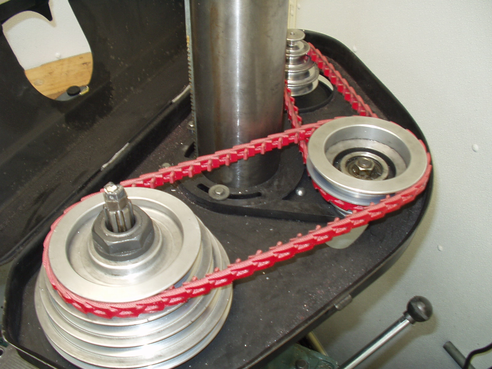
They greatly reduced the vibration and seem to improve the finish.
An easy way to see the effects of head vibration on Z-axis accuracy is to touch the cutter gently down on the surface of a test block that has been machined flat. Set zero and raise the cutter. Then move the cutter off of the block, feed in .005" and cut the surface. Stop the cutter and again gently feed down to the surface. When I do this, I see about .002" of travel. This says that the head is bouncing up and down .002" during cutting sort of like a sewing machine needle. If you are trying to hit .01", this is no big deal. In my quest for the best accuracy, this error source has got to go.
Another dynamic error source is contamination. As you cut, you are generating flecks of metal. They go everywhere. When the block being machined is removed from the vise, there is a tendency for these flecks to settle on the top of the parallels and on the fixed jaw of the vise. These flecks may only be .001" thick but that is a bolder when you are chasing tenths.
My claim is that I can cut the thickness of a block to a given accuracy at a given point. This does not mean that the plane defined by the bottom of the block is parallel to the plane defined by the top of the block. My procedure actively works to cut the thickness at the given point. Your ability to cut parallel surfaces comes into play for the rest of it. Factors such as vise ways parallel to the XY plane, spindle parallel to the Z plane, a true vise, clean surfaces, true parallels, and proper bedding of the block contribute to your overall success in this matter.
Error Source Remedies
The Shumatech DRO is an amazing design with a large following of enthusiastic users. I certainly count myself in this almost fanatical crowd. One reason for its popularity is the huge number of features packed into its software.
One nice feature of this DRO is the ability to display the raw counts from the scales after the filter software has processed them.
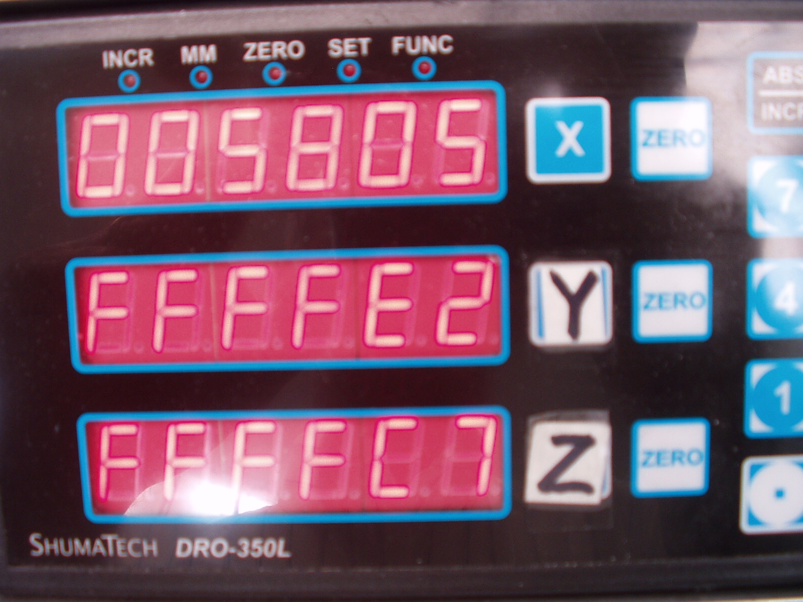
These raw counts are in hexadecimal (HEX). I believe they use 2's compliments to represent negative numbers. If you own a pocket calculator that converts between HEX and decimal, it is not hard to take the raw counts in HEX and convert them to raw counts in decimal. Additionally, if your calculator also has programming capabilities, it is not hard to have it accept the raw counts and display scale movement in steps of .0001". In this way you can side step the round off error "bug" and eliminate that .00025" error offset. Once you can see movements in steps of .0001", you can compare them to the standard decimal display on the DRO and see for yourself that the software rounds down. You can also see that the raw counts jump by the amount of the filter value.
Let me stop for a minute here, and discuss these counts from the Chinese scales. Ideally, you get 20,480 counts per inch. This means that 1 count represents .000,048,828,125". Even if the scale is not moving, the scale's electronics will be constantly changing the count down around the least significant digit. This is just electrical/thermal noise. I don't have a schematic of the electronics, but it is reasonable to assume that 1 count represents an amazingly small change in voltage or current.
Considering that Harbor Freight can made money selling these scales for $16 it truly is an achievement. Take one apart and you will see that one chip drives the display, interfaces with the buttons, and drives the data port that feeds the cable to the DRO. You can see pictures on the insides in an article on my web site.
As I mentioned in a previous section, my DRO filter threshold is set to 9. Given that each count is 1/20,480 inches, 9 counts represent .00044". If the counts are slowly increasing, the filter will absorb 9 of these counts before changing its output. In other words, it will retain 9 counts. If the counts are slowing decreasing, the filter will again absorb 9 counts before changing its output. So again it will retain 9 counts. Depending on the direction of change, the filter will always hold back 9. This translates into an uncertainty of +/- .00044". So what can be done about it?
The answer is to not use the DRO in the conventional manner on the finish cut. Rather than monitor the Z-axis while feeding in the cutter, I look at the X-axis with the help of a DTI and a homemade sine bar. For every .0001" change in the Z-axis, I see a .010" change in the X-axis. More detail later.
Taming the mill is our next challenge. We know that vibration causes head bounce, which causes the cutter to go deeper than indicated by the DRO. I can't tell you exactly how much vibration exists but am reasonably sure that given two consecutive cuts of the same depth, cutter RPM, and feed rate, the vibration will be almost identical. As you will see in the procedure, it is possible to reduce the vibration error to a point where other factors dominate.
One problem I had when trying to feed in .0001" was the gunge in my down feed mechanism. The congealed grease from 15 years of use had gotten sticky. It was a simple task to disassemble, clean, and re-grease.
When you are trying to chase these tiny numbers, it does not take much to really mess you up. After you made a light cut, there will be lots of tiny flecks of metal on the mill and possibly on your hands. If one of these flecks gets under the block or between the block and your mic, you can get a substantial error. The solution to this problem is to become a fanatic about cleanliness. Now don't laugh, but I keep a roll of toilet paper and a spray bottle of WD40 next to my mill. Every time I remove the block from my vise, I spray down all surfaces with WD40 and wipe down with clean TP. Use a clean face of TP on each wipe of the vise or you will re-contaminate surfaces. Use the same procedure on your mic anvils. Lastly, be mindful of metal particles on your hands. I do not like to wash my hands in WD40 but do try to wipe them clean with just TP. If they are really coated with metal particles, I use waterless hand cleaner. This stuff works well but does not know the difference between unwanted grease and normal hand oils. By the end of the day my hands are typically cracked and bleeding. All for the love of making swarf.
Custom Hardware
In order to achieve maximum accuracy, I had to made a special attachment for my mill. Don't panic, it is not fancy. You will need to cut a block of metal that is flat on the bottom and has a slope of about 1:100 on the top. If you can get the slope exactly at 1:100, this is nice but what is really important is that the two surfaces be dead flat. This block is going to slide on the top of the vise and be gently touched from above by a DTI. I made mine from aluminum.
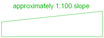
With this block we will be able to adjust the Z-axis in steps of .0001" by moving the X axis in steps of .010" (.0001"/.010" = 1/100).
Making the block out of aluminum has a nice side benefit. I am able to use a magnet to press the block against the back of the movable jaw and they do not stick together. The aluminum also does not channel the magnetic field to my DTI, which can make it stick. This arrangement makes it easy to slide the block sideways and have it stay put.
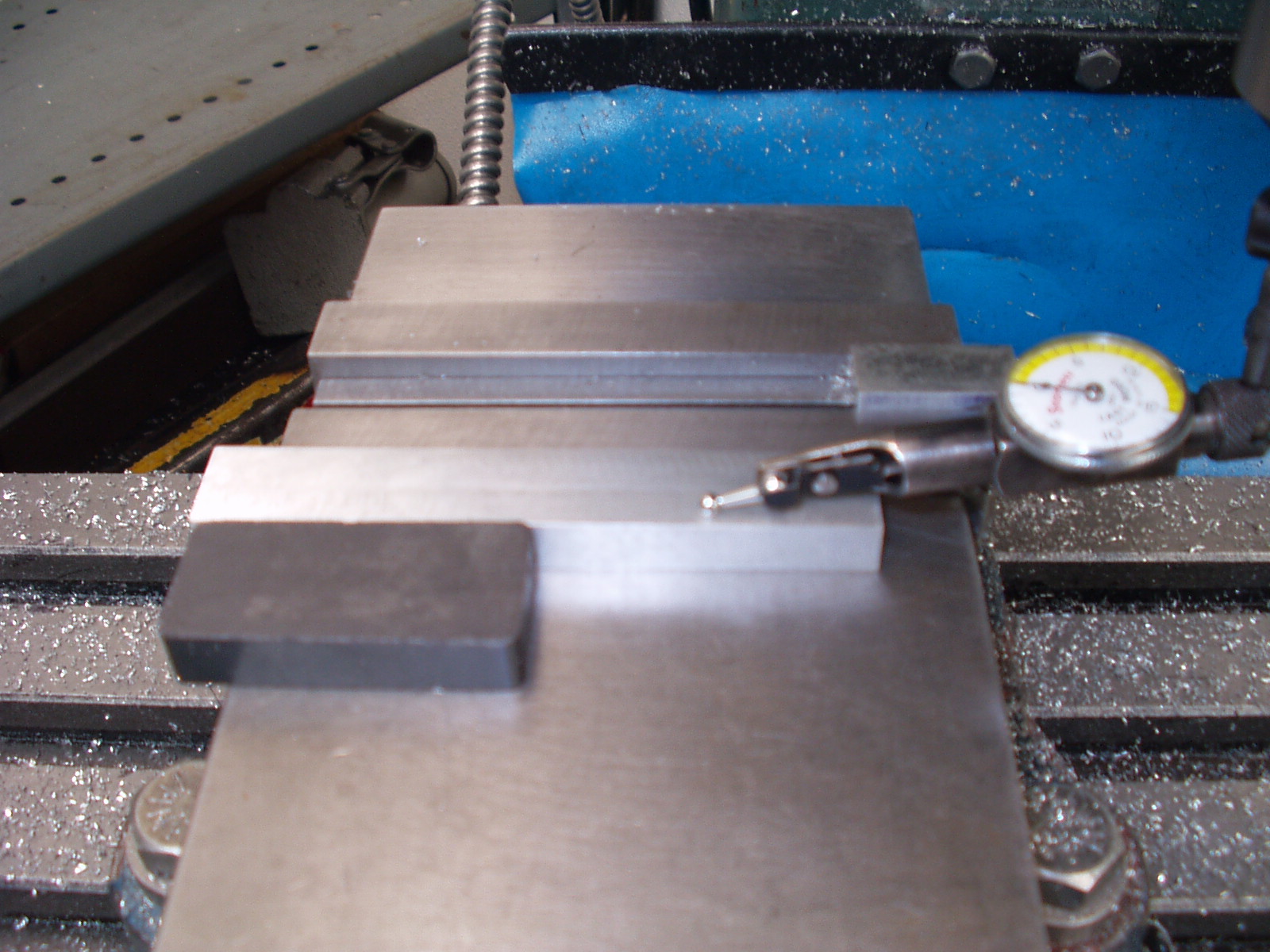
The basic idea is to mount a DTI onto the spindle and adjust the DTI support so the DTI finger rests close to the block. Set the dial of the DTI so the needle only travels .002" before reaching zero. This minimizes the force on the DTI and its support. You can then slide the block until the DTI reads zero. Since the slope is about 1:100, it is very easy to get that DTI needle right at 0. At this point the block must not move. The tiny force of the DTI is not enough to overcome the side force of the magnet against the block so that leaves both of my hands free to complete the procedure.
The next step is to move the table along the X-axis. Ideally, for every .0001" you want to lower the cutter, move the table .010". This ratio will be different for you if your slope is not 1:100. As long as you know the slope, you can use it in the calculation and accurately get .0001" steps. But wait, there is an error source that will limit your success.
How well can you repeatedly touch down your DTI and read zero? Error in placing the DTI at 0 directly contributes to overall error. You must set 0 twice and these errors can add up. By looking at the raw counts on the DRO and always moving down to touchdown, it was possible for me to see that I introduce an error of at least +/-.0001" every time. So I gain the ability to move the cutter down in increments of .0001" but with an error of around +/- .0002". Maybe over time I will get better at this procedure and get back some of this lost accuracy. The good news here is that I am setting the cutter depth within about +/- .0002" and avoiding the filter error of +/- .00044" so I'm still ahead by a factor of 2. I plan to experiment with using a magnifying glass during this procedure in hopes of hitting zero more accurately.
The Sow's Ear to Silk Purse Procedure
Not included here is the fact that all surfaces must be kept absolutely clean.
End of procedure.
Final Thoughts
I invite people to try this procedure and let me know what they learn. You do not need a DRO. Good graduated collars on your feed wheels or push rod DTIs should give similar results.
I would like to thank Brian Lamb for his guidance on this adventure. He keeps me honest and on my toes.
Enjoy,
Rick Sparber
Rgsparber@AOL.com